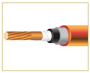
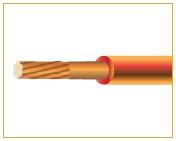
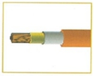
Fire Performance Cables -Draka
Why Fire Performance Cables are so important ?
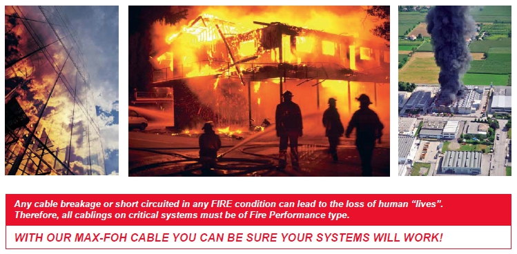
Major accidents which have resulted in the death of many innocent people, have taught us that the safety of the occupants are users in public, commercial and industrial environments is of paramount importance. Every possible safety designed to prevent and protect against loss of life and damage to property should be specified and installed.
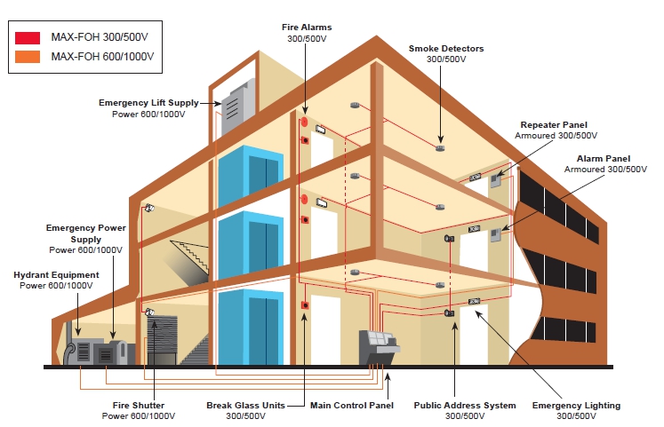
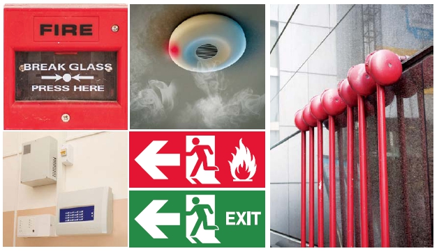
One such safety feature in the use of fire performance cables for critical safety system, Including fire alarms, emergency lighting, PA system, CCTV system, emergency power supplies and smoke & shutters.
The correct selection and installation of these “life saving” cables help ensure that in the event of an emergency, vital safety system will continue to operate to assist an orderly evacuation of the premises and to aid the emergency services in gaining quick and effective entry to deal with the hazard.
At Prysmain Group, we understand what is required form a fire performance cable and we appreciate the pressures faces by specifiers and consultant in selecting the correct cable from the range available. For nearly twenty years, our special cables have been servicing the needs of market by designing and manufacturing the widest rang of fire performance cables available today.
APPLICATION
Our fire performance cables are specifically designed to facilitate the quick and orderly evacuation of the building occupants in the events of an emergency. Purpose designed to maintain circuit integrity to a host of critical safety systems, including fire alarms, emergency lights, CCTV systems and emergency power supplied MAX-FOH
Choosing The Right Cables, and The Right Manufacturer
Issues to take note when comparing with other cables,
1. Some brands are OEM cables and carry certification from the original manufacturers.
2. Some conductor used may be undersized conductor, and hence cheaper.
3. Some brands use only one layer of mica tape for all conductor size with less than the recommended over-lapping.
4. Insulation used is cheaper PVC instead of LSHF material, hence the cable is actually not low Smoke Halogen Free compliant.
5. Cheaper polymer are used to reduce cost, but are without sufficient flame and smoke suppressant.
6. Thickness of insulation and sheathing are thinner to reduce cost.
7. Other cables may only have in-house testing reports and not certification from a recognised 3rd party verification agency.
Safety in NEVER a compromise when it comes to fire protection !
STANDARDS AND APPROVALS
BS 6387/SS 299
Part 1: 1994 – Fire, Fire with Water & Fire with Mechanical Shock Tests
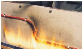
The following test is the nationally recognised United Kingdom and Singapore test used to determine if a cable is capable of maintaining circuit integrity under fire conditions, fire with water and fire with mechanical shock. These tests use a number of alternative time and temperature parameters and depending on the level achieved by the cable, a corresponding letter is assigned to denote the category the cable passed.
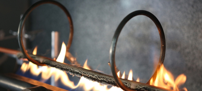
| Resistance to fire : |
Symbol |
| 650°C for 3 hours |
A |
| 750°C for 3 hours |
B |
| 950°C for 3 hours |
C |
| 950°C for 20 minutes |
S |
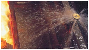
| Resistance to fire and water : |
Symbol |
| 650°C for 15 min |
W |
| Resistance to fire and mechanical shock : |
Symbol |
| 650°C for 15 minutes, with 30 second hammer blows |
X |
| 750°C for 15 minutes, with 30 second hammer blows |
B |
| 950°C for 15 minutes, with 30 second hammer blows |
C |
During the tests the cables are energized at their rated voltage.
MAX-FOH cables meet the highest categories of BS 6387 i.e. C, W & Z
| IEC 61034 – Smoke Density Test |
|
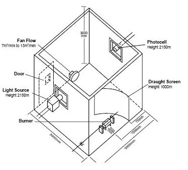
This test measures the smoke emission from electric cables during fire. The test is carried out in a 3m cubed chamber where a cable sample is subjected to fire.
The smoke emission and density are measured by transmitting a beam of light across the inside of the chambers to a photo electric cell which measures the amount of light received
All MAX-FOH cables comply to IEC 61034 requirement.
|

Additional Consideration
As well as requirements written into international and British cable standards, there are other essential criteria which designers and consultants need to consider – is the cable able to withstand voltage spikes, transmit date prevent flame propagation?
All MAX-FOH cables do comply with these additional benefits, including the added advantage that MAX-FOH requires fewer joints in a cable run compare to mineral, reducing the risk of weak links in the chain. MAX-FOH does not require complicated and is therefore quicker and easier to install.
CONSTRUCTION OF CABLE
.jpg)
| Construction |
MAX-FOH
500
mullti-cores |
MAX-FON-OSCR 500V
twisted
pair |
MAX-FOH
0.6/1KV |
MAX-FOH-I 0.6/1KV |
MAX-FOH-125 0.6/1KV |
| Conductor |
Stranded
annealed
copper |
Stranded
annealed
copper |
Stranded
annealed
copper |
Stranded annealed copper |
Stranded
annealed
copper |
Fire
Barrier |
Mica
tape |
Mica
tape |
Mica
tape |
Mica
tape |
Mica
tape |
| Insulation |
Cross-linked polythylene
(XLPE) |
Cross-linked polyethylene
(XLPE) |
Cross-linked polyethylen |
Cross-linked EVA** (XLEVA)<Orange> |
Cross-linked EVA**
(XLEVA) |
| Shield* |
Optional* |
Aluminium foil with tinned copper drain wire |
Aluminium foil with tinned copper drain wire |
- |
Aluminum foil with tinner copper drain wire |
| Filler* |
LSHF filler or polypropylene split yam |
LSHF filier or polypropylene split yam |
LSHF filier or polypripylene
yam |
- |
LSHF filier or polypripylene
yam |
Binder
Tape* |
Polyester
tape |
Polyester
tape |
Polyester
tape |
- |
Polyestes
tape |
| Bedding |
Low smoke
halogen
free (LSHF) compound
(black) |
Low smoke
halogen
free (LSHF) compound
(black) |
Low smoke
halogen
free (LSHF) compound
(black) |
- |
Low smoke
halogen
free (LSHF) compound
(black) |
| Amour*/# |
Galvanised steel
wire
(aluminium or copper wire for single core) |
Galvanised steel
wire
(aluminium or copper wire for single core) |
Galvanised steel
wire
(aluminium or copper wire for single core) |
- |
Galvanised steel wire
(aluminium or copper wire for single core) |
| Sheath |
Low smoke halogen free(LSHF)
compound
(Orange) |
Low smoke halogen free(LSHF)
compound
(Orange) |
Low smoke halogen free(LSHF)
compound
(Orange) |
- |
Low smoke halogen free
(LSHF) compound (Orange) |
Optional: Depending on requirement
# Braided armour also available on request
XLEVA (Cross-linked Ethylene Vinyl Acetate) material used are suitable for operating temperature of 110°C up to 125°C
XLPE (Cross-linked Polyethylene) material used for operating temperature of 90°C
No. of cores
|
Identification of cores |
| Option 1 |
Option 2 |
| 1 |
Natural |
Other color on request |
| 2 |
Brown, blue |
Red, Black |
| 3 |
Brown, Black, Grey |
Red, Yellow, Blue |
| 4 |
Brown, Black, Grey, Blue |
Red, Yellow, Blue, Black |
| 5 |
Brown, Black, Grey, Blue |
Red, Yellow, Blue, Black, Green/Yellow |
| 6 and above |
Black with white numbering
|
Note: Special construction and design to customers’ specification can be upon request
Applicable Stanards
IEC 60502-1
AS/NZS 3198 |
Extruded solid dielectric insulated power cable for rated voltage of 1 kV up to 30kV |
|
IEC 60228
BS 6360 AS/NZS 1125
|
Conductor of insulated cables |
|
IEC 60754-1
BS 6425-2 AS/NZS 1160.5
|
Test on gases evolved during combustion of electric cables-Determination of the amount of halogen acid gases
|
|
IEC 60754-2
BS 6426-2 AS/NZS 1160.5.4
|
Test on gases evolved during combustion of electric cables-Determination of degree of acidity of gases evolved by measuring pH and conductivity
|
|
IEC 60331
AS/NZS 1160.5.5
|
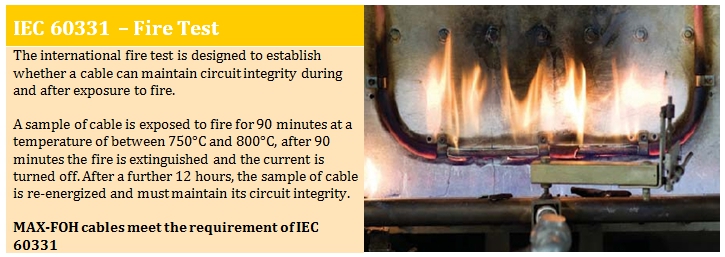
Fire resistant characteristics of electric cable (750°C for 90 minutes) |
|
IEC 60332 Part 1
BS 4066 Part 1
|
Test on electric cables under fire conditions-Test on a single vertical insulated wire or cable
|
|
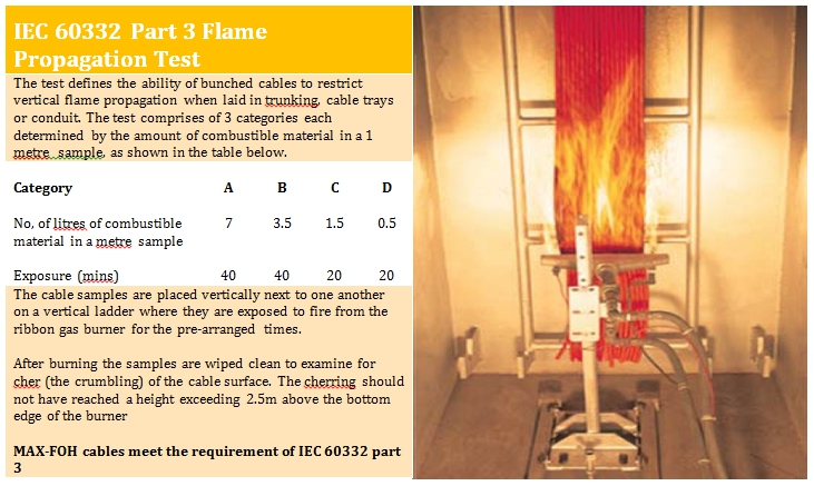
IEC 60332 Part 3
BS 4066 Part 3 Category A,B,C/ AS/NZS 1660.5.1
|
Measurement of smoke density of cables burning under defined conditions |
|
BS 6387
SS 299 Part 1
|
Performance requirements for cables required to maintain circuit integrity under fire condition
Category C : tested at 950°C for 3 hours
Category W : fire with water
Category Z : fire with mechanical shock
|
| BS 6724 |
Armoured cables for electricity supply having thermosetting insulation with low emission of smoke and corrosive gases when affected by fire |
| BS 7211 |
Thermosetting insulated cables (non-armoured) For electric power and lighting with low emission of smoke and corrosive gases when affected by fire |
| BS 7846 |
600/1000V armoured fire-resistant electric cables having low emission of smoke and corrosive gases when affected by fire |
| AS/NZS 3013 |
Electrical installations – Classification of the fire and mechanical performance of wiring system |
* Standards applied will vary depending on cable construction
Comparision between test standards IEC 60331 Part 21 & SS 299 Part 1
| Ref |
Description |
IEC 60331 Part 21 |
0.6/1 kV cables |
Data cables |
Optical fiber cables |
SS 299
Part 1 |
0.6/1 kV cables |
Data cables |
Optical fiber cables |
| 1 |
Resistance to
FIRE alone
Flame
temperature / Duration
|
750°C/90 min
|
✔ |
✔ |
✔ |
Cat A - 650°C/3hr.
Cat B - 750°C/3hr.
Cat C - 950°C/3hr.
Cat S - 650°C/20min.
|
✔
|
|
|
| 2 |
Resistance to FIRE with mechanical shock
Flame temperature / Duration
Mechanical shock
|
830°C/120min
Every 5min
|
✔ |
|
|
Cat X - 650°C/3hr.
Cat Y - 750°C/3hr.
Cat Z - 950°C/3hr.
Every 30 sec.
|
✔ |
|
|
| 3 |
Resistance to FIRE with water spray
Flame temperature / Duration
|
Not available |
|
|
|
Cat w - 650°C/15min. |
✔ |
|
|
| 4 |
Other tests
Electrical requirements
for completed cables
Bending characteristics
Resistance of cable to impact
|
Not available |
✔ |
|
|
Available |
✔ |
|
|
MAX-FOH Insulate and sheathed MAX-FOH (OSCR) Insulate and sheathed
500Vac. Unarmored and Armoured with Shield

| Conductor |
Plain stranded
annealed copper Class 2 |
Plain stranded
annealed copper Class 2 |
|
0.5 mm² up to 4 mm² |
0.5 mm² up to 2.5 mm² |
| Fire Barrier : |
Mica Glass Tape |
Mica Glass Tape |
| Insulation : |
XLPE compound |
XLPE compound |
| Bedding : |
LSHF compound |
LSHF compound |
| Shield : |
Optional |
Aluminium foil with tinned copper drain wire |
| Armouring : |
Optional |
Optional |
| Sheate : |
LSHF compound |
LSHF compound |
| UV Resistance : |
Optional |
Optional |
| Anti -Termite : |
Optional |
Optional |
| Insulation Colours : |
Blue, Brown, Black, Grey |
Black & White-numbering |
| Bedding Colours : |
Black |
Black |
| Sheath Colours : |
Orange (Standard) |
Orange (Standard) |
Reference
Standard : |
BSEN 50288-7 |
BSEN 50288-7 |
| Voltage : U๐/U |
500V |
500V |
| Circuit Integrity : Up to 1 mm² |
IEC 60331-21,SS 299-1 |
IEC 60331-21,SS 299-1 |
| 1.5 mm² up to Max. mm² |
IEC 60331-21,SS 299-1
BS 6387 Cat C, W, Z |
IEC 60331-21,SS 299-1
BS 6387 Cat C, W, Z |
| Test Standard |
|
|
| Flame Retardant : |
|
|
| Single Vertical cable |
ICE 60223-1, BS 4066-1,
BS EN 50266-1
|
ICE 60223-1, BS 4066-1,
BS EN 50266-1 |
| Bunched cables |
ICE 60223-1, BS 4066-3,
BS EN 50266-2 |
ICE 60223-1, BS 4066-3,
BS EN 50266-2 |
| Halogen gases : |
ICE 60754-1, BS 6425-1,
BS EN 50267-1 |
ICE 60754-1, BS 6425-1,
BS EN 50267-1 |
Corrosiveness &
Conductivity : |
ICE 60754-2, BS 6425-2,
BS EN 50267-2 |
ICE 60754-2, BS 6425-2,
BS EN 50267-2 |
| Smoke Emission : |
IEC 61034-2, BS 7622-2,
BS EN 61034-2 |
IEC 61034-2, BS 7622-2,
BS EN 61034-2 |
500Vac. Unarmoured and Armoured Fire Resistant Cables
.jpg)
|
core
|
Unarmoured /cable |
Armoured /cable |
| Nominal area of conductor |
No.& Diameter of wires |
Insulation Thickness |
Sheath Thickness |
Approx. diameter overall |
Approx. weight |
Bedding Thickness |
Armour wire Thickness |
Sheath Thickness |
Approx. diameter overall |
Approx. weight |
| mm² |
No./mm |
mm |
mm |
mm |
Kg/km |
mm |
mm |
mm |
mm |
Kg/km |
| 1 |
0.5 |
7/0.30 |
0.6 |
0.8 |
4.8 |
27 |
- |
- |
- |
- |
- |
| 0.75 |
7/0.37 |
0.6 |
0.8 |
5.0 |
31 |
- |
- |
- |
- |
- |
| 1 |
7/0.43 |
0.6 |
0.8 |
5.2 |
35 |
|
|
|
|
|
| 1.5 |
7/0.53 |
0.6 |
0.9 |
5.7 |
45 |
|
|
|
|
|
| 2.5 |
7/0.67 |
0.6 |
0.9 |
6.3 |
59 |
|
|
|
|
|
| 4 |
7/0.85 |
0.6 |
0.9 |
6.9 |
77 |
|
|
|
|
|
| 2 |
0.5 |
7/0.30 |
0.7 |
1.0 |
8.4 |
89 |
1.0 |
0.9 |
1.4 |
13.6 |
348 |
| 0.75 |
7/0.37 |
0.7 |
1.0 |
8.9 |
101 |
1.0 |
0.9 |
1.4 |
14.1 |
371 |
| 1 |
7/0.43 |
0.7 |
1.0 |
9.2 |
112 |
1.0 |
0.9 |
1.4 |
14.4 |
392 |
| 1.5 |
7/0.53 |
0.7 |
1.0 |
9.8 |
132 |
1.0 |
0.9 |
1.4 |
15.0 |
428 |
| 2.5 |
7/0.67 |
0.7 |
1.1 |
11.3 |
181 |
1.0 |
0.9 |
1.4 |
15.1 |
454 |
| 4 |
7/0.85 |
0.7 |
1.1 |
12.3 |
232 |
1.1 |
0.9 |
1.5 |
16.6 |
551 |
3
|
0.5 |
7/0.30 |
0.6 |
1.0 |
9.0 |
97 |
1.0 |
0.9 |
1.4 |
14.2 |
368 |
| 0.75 |
7/0.37 |
0.6 |
1.0 |
9.4 |
111 |
1.0 |
0.9 |
1.4 |
14.6 |
394 |
| 1 |
1/0.43 |
0.6 |
1.0 |
9.8 |
125 |
1.0 |
0.9 |
1.5 |
15.0 |
418 |
| 1.5 |
7/0.53 |
0.6 |
1.1 |
10.5 |
151 |
1.0 |
0.9 |
1.5 |
15.9 |
469 |
| 2.5 |
7/0.67 |
0.7 |
1.1 |
12.0 |
208 |
1.0 |
0.9 |
1.5 |
16.0 |
504 |
| 4 |
7/0.85 |
0.7 |
1.0 |
13.2 |
273 |
1.1 |
0.9 |
1.4 |
17.3 |
610 |
| 4 |
0.5 |
7/0.30 |
0.6 |
1.0 |
9.8 |
112 |
1.0 |
0.9 |
1.5 |
15.0 |
404 |
| 0.75 |
7/0.37 |
0.6 |
1.0 |
10.3 |
130 |
1.0 |
0.9 |
1.5 |
15.7 |
442 |
| 1 |
1/0.43 |
0.6 |
1.0 |
10.7 |
146 |
1.0 |
0.9 |
1.5 |
16.1 |
471 |
| 1.5 |
7/0.53 |
0.6 |
1.1 |
11.7 |
184 |
1.1 |
0.9 |
1.5 |
17.1 |
532 |
| 2.5 |
7/0.67 |
0.7 |
1.1 |
13.2 |
248 |
1.1 |
0.9 |
1.5 |
17.2 |
578 |
| 4 |
7/0.85 |
0.7 |
1.2 |
14.7 |
337 |
1.1 |
0.9 |
1.5 |
18.5 |
692 |
E Unarmoured fire resistant cables
F Armoured fire resistant cables
* Multicore unarmoured and armoured fire resistant cables are available upon request
500V, Unarmored and Armoured Shielded Fire Resistant Cables

|
core
|
Unarmoured /cable |
Armoured /cable |
| Nominal area of conductor |
No.& Diameter of wires |
Insulation Thickness |
Sheath Thickness |
Approx. diameter overall |
Approx. weight |
Bedding Thickness |
Armour wire Thickness |
Sheath Thickness |
Approx. diameter overall |
Approx. weight |
| mm² |
No./mm |
mm |
mm |
mm |
Kg/km |
mm |
mm |
mm |
mm |
Kg/km |
1
|
0.5 |
7/0.30 |
0.6 |
1.0 |
8.7 |
69 |
1.0 |
0.9 |
1.3 |
13.8 |
327 |
| 0.75 |
7/0.37 |
0.6 |
1.0 |
9.1 |
78 |
1.0 |
0.9 |
1.3 |
14.2 |
347 |
| 1 |
1/0.43 |
0.6 |
1.0 |
9.5 |
86 |
1.0 |
0.9 |
1.3 |
14.6 |
364 |
| 1.5 |
7/0.53 |
0.6 |
1.1 |
10.1 |
101 |
1.0 |
0.9 |
1.3 |
15.2 |
395 |
| 2.5 |
7/0.67 |
0.7 |
1.1 |
11.5 |
136 |
1.0 |
0.9 |
1.3 |
16.6 |
467 |
|
core
|
Unarmoured /cable |
Armoured /cable |
| Nominal area of conductor |
No.& Diameter of wires |
Insulation Thickness |
Sheath Thickness |
Approx. diameter overall |
Approx. weight |
Bedding Thickness |
Armour wire Thickness |
Sheath Thickness |
Approx. diameter overall |
Approx. weight |
| mm² |
No./mm |
mm |
mm |
mm |
Kg/km |
mm |
mm |
mm |
mm |
Kg/km |
| 2 |
0.5 |
7/0.30 |
0.6 |
1.1 |
13.0 |
129 |
1.1 |
1.25 |
1.3 |
18.8 |
602 |
| 0.75 |
7/0.37 |
0.6 |
1.2 |
13.9 |
154 |
1.2 |
1.25 |
1.4 |
19.9 |
666 |
| 1 |
1/0.43 |
0.6 |
1.2 |
14.5 |
171 |
1.2 |
1.25 |
1.4 |
20.5 |
703 |
| 1.5 |
7/0.53 |
0.6 |
1.2 |
15.5 |
203 |
1.2 |
1.25 |
1.4 |
21.5 |
768 |
| 2.5 |
7/0.67 |
0.7 |
1.3 |
17.5 |
274 |
1.3 |
1.25 |
1.4 |
23.9 |
926
|
|
core
|
Unarmoured /cable |
Armoured /cable |
| Nominal area of conductor |
No.& Diameter of wires |
Insulation Thickness |
Sheath Thickness |
Approx. diameter overall |
Approx. weight |
Bedding Thickness |
Armour wire Thickness |
Sheath Thickness |
Approx. diameter overall |
Approx. weight |
| mm² |
No./mm |
mm |
mm |
mm |
Kg/km |
mm |
mm |
mm |
mm |
Kg/km |
| 3 |
0.5 |
7/0.30 |
0.6 |
1.2 |
14.1 |
164 |
1.2 |
1.25 |
1.4 |
20.1 |
682 |
| 0.75 |
7/0.37 |
0.6 |
1.2 |
14.8 |
188 |
1.2 |
1.25 |
1.4 |
20.8 |
732 |
| 1 |
1/0.43 |
0.6 |
1.2 |
15.4 |
211 |
1.2 |
1.25 |
1.4 |
21.4 |
777 |
| 1.5 |
7/0.53 |
0.6 |
1.3 |
16.7 |
263 |
1.2 |
1.25 |
1.5 |
22.9 |
884 |
| 2.5 |
7/0.67 |
0.7 |
1.4 |
19.1 |
361 |
1.3 |
1.25 |
1.6 |
25.5 |
1075
|
|
core
|
Unarmoured /cable |
Armoured /cable |
| Nominal area of conductor |
No.& Diameter of wires |
Insulation Thickness |
Sheath Thickness |
Approx. diameter overall |
Approx. weight |
Bedding Thickness |
Armour wire Thickness |
Sheath Thickness |
Approx. diameter overall |
Approx. weight |
| mm² |
No./mm |
mm |
mm |
mm |
Kg/km |
mm |
mm |
mm |
mm |
Kg/km |
| 4 |
0.5 |
7/0.30 |
0.6 |
1.3 |
15.4 |
195 |
1.2 |
1.25 |
1.4 |
21.4 |
760 |
| 0.75 |
7/0.37 |
0.6 |
1.3 |
16.5 |
234 |
1.3 |
1.25 |
1.5 |
22.7 |
846 |
| 1 |
1/0.43 |
0.6 |
1.3 |
17.2 |
264 |
1.3 |
1.25 |
1.5 |
23.4 |
901 |
| 1.5 |
7/0.53 |
0.6 |
1.3 |
18.4 |
321 |
1.3 |
1.25 |
1.6 |
24.8 |
1012 |
| 2.5 |
7/0.67 |
0.7 |
1.4 |
21.0 |
444 |
1.4 |
1.25 |
1.7 |
27.6 |
1241 |
G Unarmoured fire resistant cables
H Armoured fire resistant cables
* Multipairs unarmoured and armoured shielded fire resistant cables are available upon request
| Conductor |
Plain stranded
annealed copper Class 2 |
Plain stranded
annealed copper Class 2 |
Plain stranded annealed copper Class 2 |
Plain stranded annealed copper Class 2 |
|
1.5 mm² up to 630 mm² |
1.5 mm² up to 630 mm² |
1.5 mm² up to 630 mm²** |
1.5 mm² up to 630 mm²** |
| Fire Barrier : |
Mica Glass Tape |
Mica Glass Tape |
Mica Glass Tape |
Mica Glass Tape |
| Insulation : |
XLPE compound |
XLPE compound |
XLPE compound |
XLPE compound |
| Bedding : |
- |
LSHF compound |
- |
- |
| Armouring : |
- |
Aluminium foil with tinned copper drain wire |
- |
- |
| Sheate : |
LSHF compound |
LSHF compound |
- |
LSHF compound |
| UV Resistance : |
Optional |
Optional |
Optional |
Optional |
| Anti -Termite : |
Optional |
Optional |
Optional |
Optional |
| Insulation Colours : |
Natural |
Natural |
Orange (standard) |
Whitle |
| Bedding Colours : |
- |
Black |
- |
- |
| Sheath Colours : |
Orange (Standard) |
Orange
(Standard) |
Orange
(Standard) |
Orange
(Standard) |
| Voltage : U๐/U |
600/1000V |
600/1000V |
600/1000V |
600/1000V |
| Circuit Integrity : Up to 1 mm² |
ICE 60331, SS 299-1/BS 6387 Cat C,W,Z(for 300/500V, 450/750V, 600/1000V) |
ICE 60331, SS 299-1/BS 6387 Cat C,W,Z(for 300/500V, 450/750V, 600/1000V) |
ICE 60331, SS 299-1/BS 6387 Cat C,W,Z(for 300/500V, 450/750V, 600/1000V) |
ICE 60331, SS 299-1/BS 6387 Cat C,W,Z(for 300/500V, 450/750V, 600/1000V) |
| Test Standard |
|
|
|
|
| Flame Retardant: |
|
|
|
|
| Single Vertical cable |
ICE 60332-1, BS 4066-1, BS EN 50266-1
|
ICE 60332-1, BS 4066-1, BS EN 50266-1 |
ICE 60332-1, BS 4066-1, BS EN 50266-1 |
ICE 60332-1, BS 4066-1, BS EN 50266-1 |
| Bunched cables |
ICE 60332-3, BS 4066-3, BS EN 50266-2 |
ICE 60332-3, BS 4066-3, BS EN 50266-2 |
ICE 60332-3, BS 4066-3, BS EN 50266-2 |
ICE 60332-3, BS 4066-3, BS EN 50266-2 |
| Halogen gases : |
ICE 60754-1, BS 6425-2, BS EN 50267-2-1 |
ICE 60754-1, BS 6425-2, BS EN 50267-2-1 |
ICE 60754-1, BS 6425-2, BS EN 50267-2-1 |
ICE 60754-1, BS 6425-2, BS EN 50267-2-1 |
Corrosiveness &
Conductivity : |
ICE 60754-2, BS 6425-2, BS EN 50267-2-2 |
ICE 60754-2, BS 6425-2, BS EN 50267-2-2 |
ICE 60754-2, BS 6425-2, BS EN 50267-2-2 |
ICE 60754-2, BS 6425-2, BS EN 50267-2-2 |
| Smoke Emission : |
ICE 61034-2, BS 7622-2, BS EN 61034-2 |
ICE 61034-2, BS 7622-2, BS EN 61034-2 |
ICE 61034-2, BS 7622-2, BS EN 61034-2 |
ICE 61034-2, BS 7622-2, BS EN 61034-2 |
Cable Type : MAX-FOH-I / MAX-FOH
Constructions : Insulated, non-sheathed Insulated and sheathed
Material : Composition Copper/MGT/XLEVA Copper/MGT/XLPE/LSHF
Standard : IEC 60502-1
Voltage : 600/1000V
Single core:
| Conductor cross sectional area |
No.& Diameter of wires |
Insulation Thickness |
Cable overall diameter |
Cable weight |
Insulation Thickness |
Sheath Thickness |
Cable overall diameter |
Cable weight |
| 1 x 1.5 |
7/0.53 |
0.7 |
4.0 |
30 |
0.7 |
1.4 |
6.6 |
60 |
| 1 x 2.5 |
7/0.67 |
0.8 |
4.5 |
40 |
0.7 |
1.4 |
7.0 |
73 |
| 1 x 4 |
7/0.85 |
1.0 |
5.4 |
60 |
0.7 |
1.4 |
7.6 |
93 |
| 1 x 6 |
7/1.04 |
1.0 |
6.0 |
90 |
0.7 |
1.4 |
8.1 |
120 |
| 1 x 10 |
7/1.35 |
1.0 |
7.0 |
130 |
0.7 |
1.4 |
9.0 |
160 |
| 1 x 16 |
7/1.70 |
1.0 |
8.1 |
190 |
0.7 |
1.4 |
10.1 |
230 |
| 1 x 25 |
7/2.14 |
1.2 |
9.8 |
300 |
0.7 |
1.4 |
12.0 |
330 |
| 1 x 35 |
19/1.53 |
1.2 |
11.0 |
400 |
0.7 |
1.4 |
13.3 |
450 |
| 1 x 50 |
19/1.78 |
1.4 |
12.8 |
540 |
0.7 |
1.4 |
14.8 |
600 |
| 1 x 70 |
19/2.14 |
1.4 |
14.5 |
740 |
1.1 |
1.4 |
16.7 |
810 |
| 1 x 95 |
19/2.52 |
1.6 |
16.9 |
1020 |
1.1 |
1.5 |
18.9 |
1100 |
| 1 x 120 |
37/2.03 |
1.6 |
18.4 |
1250 |
1.2 |
1.5 |
20.9 |
1340 |
| 1 x 150 |
37/2.25 |
1.6 |
20.7 |
1540 |
1.4 |
1.6 |
23.1 |
1650 |
| 1 x 185 |
37/2.52 |
2.0 |
23.0 |
1930 |
1.6 |
1.7 |
25.6 |
2630 |
| 1 x 240 |
61/2.25 |
2.2 |
23.0 |
2510 |
1.7 |
1.4 |
28.4 |
3260 |
| 1 x 300 |
61/2.52 |
2.4 |
28.9 |
3130 |
1.8 |
1.8 |
31.3 |
3260 |
| 1 x 400 |
61/2.85 |
2.6 |
32.1 |
3960 |
2.0 |
1.9 |
34.7 |
4100 |
| 1 x 500 |
61/3.20 |
2.8 |
39.7 |
6330 |
2.2 |
2.1 |
38.8 |
5180 |
| 1 x 630 |
127/2.52 |
- |
- |
- |
2.4 |
2.2 |
43.3 |
6590 |
| 1 x 800 |
127/2.85 |
- |
- |
- |
2.6 |
2.3 |
48.0 |
8300 |
| 1 x 1000 |
127/3.20 |
- |
- |
- |
2.8 |
2.5 |
53.5 |
10470 |
Cable Type : MAX-FOH-AWAConstructions : Insulated, non-sheathed
Material : Composition Copper/MGT/XLEVA Copper/MGT/XLPE/LSHF
Standard : IEC 60502-1
Voltage : 600/1000V
Single core:
| Conductor cross sectional area |
No.& Diameter of wires |
Diameter under armour |
Armour
wires diameter
|
Sheath Thickness |
Cable overall diameter |
Cable weight |
| 1 x 1.5 |
7/0.53 |
- |
- |
- |
- |
- |
| 1 x 2.5 |
7/0.67 |
- |
- |
- |
- |
- |
| 1 x 4 |
7/0.85 |
- |
- |
- |
- |
- |
| 1 x 6 |
7/1.04 |
- |
- |
- |
- |
- |
| 1 x 10 |
7/1.35 |
- |
- |
- |
- |
- |
| 1 x 16 |
7/1.70 |
- |
- |
- |
- |
- |
| 1 x 25 |
7/2.14 |
- |
- |
- |
- |
- |
| 1 x 35 |
19/1.53 |
- |
- |
- |
- |
- |
| 1 x 50 |
19/1.78 |
13.8 |
1.25 |
1.5 |
19.5 |
800 |
| 1 x 70 |
19/2.14 |
15.7 |
1.25 |
1.5 |
21.7 |
1130 |
| 1 x 95 |
19/2.52 |
17.7 |
1.25 |
1.6 |
23.9 |
1450 |
| 1 x 120 |
37/2.03 |
19.4 |
1.6 |
1.6 |
26.3 |
1770 |
| 1 x 150 |
37/2.25 |
21.4 |
1.6 |
1.7 |
28.5 |
2130 |
| 1 x 185 |
37/2.52 |
23.7 |
1.6 |
1.8 |
31.0 |
2580 |
| 1 x 240 |
61/2.25 |
26.5 |
1.6 |
1.9 |
34.0 |
3220 |
| 1 x 300 |
61/2.52 |
29.2 |
1.6 |
1.9 |
36.7 |
3890 |
| 1 x 400 |
61/2.85 |
32.8 |
2.0 |
2.1 |
41.5 |
5000 |
| 1 x 500 |
61/3.20 |
36.5 |
2.0 |
2.2 |
45.4 |
6150 |
| 1 x 630 |
127/2.52 |
40.8 |
2.0 |
2.3 |
49.9 |
7670 |
| 1 x 800 |
127/2.85 |
45.7 |
2.5 |
2.5 |
56.2 |
9780 |
| 1 x 1000 |
127/3.20 |
50.8 |
2.5 |
2.6 |
61.5 |
12080 |
|
MAX-FOH Insulated and sheathed
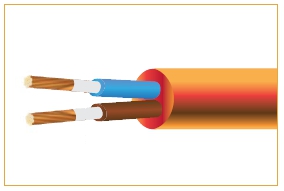
|
MAX-FOH-SWA Insulated, armoured and sheathed
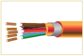
|
|
MAX-FOH-125 Insulated and sheathed
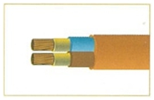
|
MAX-FOH-125-SWA Insulated, armoured and sheathed
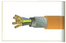
|
| Conductor |
Plain stranded
annealed copper Class 2 |
Plain stranded
annealed copper Class 2 |
Plain stranded annealed copper Class 2 |
Plain stranded annealed copper Class 2 |
|
1.5 mm² up to 400 mm² |
1.5 mm² up to 400 mm² |
1.5 mm² up to 400 mm²** |
1.5 mm² up to 400 mm²** |
| Fire Barrier : |
Mica Glass Tape |
Mica Glass Tape |
Mica Glass Tape |
Mica Glass Tape |
| Insulation : |
XLPE compound |
XLPE compound |
XLPE compound |
XLPE compound |
| Bedding : |
- |
LSHF compound |
- |
- |
| Armouring : |
- |
Aluminium foil with tinned copper drain wire |
- |
- |
| Sheate : |
LSHF compound |
LSHF compound |
- |
LSHF compound |
| UV Resistance : |
Optional |
Optional |
Optional |
Optional |
| Anti -Termite : |
Optional |
Optional |
Optional |
Optional |
| Bedding Colours : |
- |
Black |
- |
- |
| Sheath Colours : |
Orange
(Standard) |
Orange
(Standard) |
Orange
(Standard) |
Orange
(Standard) |
| Voltage : U๐/U |
600/1000V |
600/1000V |
600/1000V |
600/1000V |
| Circuit Integrity : Up to 1 mm² |
ICE 60331, SS 299-1/BS 6387 Cat C,W,Z(for 300/500V, 450/750V, 600/1000V) |
ICE 60331, SS 299-1/BS 6387 Cat C,W,Z(for 300/500V, 450/750V, 600/1000V) |
ICE 60331, SS 299-1/BS 6387 Cat C,W,Z(for 300/500V, 450/750V, 600/1000V) |
ICE 60331, SS 299-1/BS 6387 Cat C,W,Z(for 300/500V, 450/750V, 600/1000V) |
| Test Standard |
|
|
|
|
| Flame Retardant: |
|
|
|
|
| Single Vertical cable |
ICE 60332-1, BS 4066-1, BS EN 50266-1
|
ICE 60332-1, BS 4066-1, BS EN 50266-1 |
ICE 60332-1, BS 4066-1, BS EN 50266-1 |
ICE 60332-1, BS 4066-1, BS EN 50266-1 |
| Bunched cables |
ICE 60332-3, BS 4066-3, BS EN 50266-2 |
ICE 60332-3, BS 4066-3, BS EN 50266-2 |
ICE 60332-3, BS 4066-3, BS EN 50266-2 |
ICE 60332-3, BS 4066-3, BS EN 50266-2 |
| Halogen gases : |
ICE 60754-1, BS 6425-2, BS EN 50267-2-1 |
ICE 60754-1, BS 6425-2, BS EN 50267-2-1 |
ICE 60754-1, BS 6425-2, BS EN 50267-2-1 |
ICE 60754-1, BS 6425-2, BS EN 50267-2-1 |
Corrosiveness &
Conductivity : |
ICE 60754-2, BS 6425-2, BS EN 50267-2-2 |
ICE 60754-2, BS 6425-2, BS EN 50267-2-2 |
ICE 60754-2, BS 6425-2, BS EN 50267-2-2 |
ICE 60754-2, BS 6425-2, BS EN 50267-2-2 |
| Smoke Emission : |
ICE 61034-2, BS 7622-2, BS EN 61034-2 |
ICE 61034-2, BS 7622-2, BS EN 61034-2 |
ICE 61034-2, BS 7622-2, BS EN 61034-2 |
ICE 61034-2, BS 7622-2, BS EN 61034-2 |
Cable Type : MAX-FOH / MAX-FOH-SWA
Constructions : XLPE Insulated, LSHF bedding, Steel weir armoured and LSHF sheathed
Material Composition : Copper/MGT/XLPE/LSHF
Standard : 600/1000V
2 core:
| Conductor cross sectional area |
No.& Diameter of wires |
Insulation Thickness |
Sheath Thickness |
Cable overall diameter |
Cable weight |
Diamete |
Armour
wires diameter |
Sheath Thickness |
Cable overall diameter |
Cable weight |
| 2 x 1.5 |
7/0.53 |
0.7 |
1.8 |
11.3 |
180 |
9.7 |
0.9 |
1.8 |
15.1 |
435 |
| 2 x 2.5 |
7/0.67 |
0.7 |
1.8 |
12.1 |
210 |
1.5 |
0.9 |
1.8 |
15.9 |
493 |
| 2 x 4 |
7/0.85 |
0.7 |
1.8 |
13.2 |
270 |
11.6 |
0.9 |
1.8 |
17.0 |
576 |
| 2 x 6 |
7/1.04 |
0.7 |
1.8 |
14.3 |
340 |
12.7 |
1.25 |
1.8 |
18.8 |
777 |
| 2 x 10 |
7/1.35 |
0.7 |
1.8 |
16.3 |
380 |
14.7 |
1.25 |
1.8 |
20.8 |
901 |
| 2 x 16 |
7/1.70 |
0.7 |
1.8 |
19.7 |
540 |
16.9 |
1.25 |
1.8 |
23.5 |
1230 |
| 2 x 25 |
7/2.14 |
0.9 |
1.8 |
22.5 |
780 |
20.4 |
1.6 |
1.8 |
27.7 |
1780 |
| 2 x 35 |
19/1.53 |
0.9 |
1.8 |
25.3 |
1030 |
23.3 |
1.6 |
1.8 |
30.4 |
2150 |
| 2 x 50 |
19/1.78 |
1.0 |
1.8 |
28.4 |
1320 |
26.3 |
1.6 |
1.9 |
33.7 |
2600 |
| 2 x 70 |
19/2.14 |
1.1 |
1.8 |
32.4 |
1800 |
30.3 |
1.6 |
2.0 |
37.9 |
3300 |
| 2 x 95 |
19/2.52 |
1.1 |
2.0 |
37.0 |
2450 |
34.9 |
1.6 |
2.1 |
43.5 |
4570 |
| 2 x 120 |
37/2.03 |
1.2 |
2.1 |
40.6 |
3000 |
38.3 |
2.0 |
2.2 |
47.1 |
5310 |
| 2 x 150 |
37/2.25 |
1.4 |
2.2 |
44.9 |
3710 |
42.4 |
2.0 |
2.4 |
51.6 |
6280 |
| 2 x 185 |
37/2.52 |
1.6 |
2.3 |
19.8 |
4570 |
47.5 |
2.0 |
2.5 |
57.9 |
8150 |
| 2 x 240 |
61/2.25 |
1.7 |
2.5 |
56.0 |
5920 |
53.3 |
2.5 |
2.7 |
64.1 |
9920 |
| 2 x 300 |
61/2.52 |
1.8 |
2.6 |
61.6 |
7280 |
59.1 |
2.5 |
2.9 |
70.3 |
11790 |
3 core:
| Conductor cross sectional area |
No.& Diameter of wires |
Insulation Thickness |
Sheath Thickness |
Cable overall diameter |
Cable weight |
Diamete |
Armour
wires diameter |
Sheath Thickness |
Cable overall diameter |
Cable weight |
| 3 x 1.5 |
7/0.53 |
0.7 |
1.8 |
12.0 |
200 |
10.3 |
0.9 |
1.8 |
15.7 |
477 |
| 3 x 2.5 |
7/0.67 |
0.7 |
1.8 |
12.8 |
245 |
11.2 |
0.9 |
1.8 |
16.6 |
544 |
| 3 x 4 |
7/0.85 |
0.7 |
1.8 |
14.0 |
315 |
12.3 |
0.9 |
1.8 |
17.7 |
641 |
| 3 x 6 |
7/1.04 |
0.7 |
1.8 |
15.2 |
400 |
13.6 |
1.25 |
1.8 |
19.7 |
867 |
| 3 x 10 |
7/1.35 |
0.7 |
1.8 |
17.3 |
500 |
15.7 |
1.25 |
1.8 |
21.8 |
1033 |
| 3 x 16 |
7/1.70 |
0.7 |
1.8 |
19.9 |
720 |
18.1 |
1.25 |
1.8 |
24.7 |
1460 |
| 3 x 25 |
7/2.14 |
0.9 |
1.8 |
24.1 |
1060 |
22.0 |
1.6 |
1.8 |
29.2 |
2130 |
| 3 x 35 |
19/1.53 |
0.9 |
1.8 |
27.0 |
1390 |
24.9 |
1.6 |
1.8 |
32.1 |
2600 |
| 3 x 50 |
19/1.78 |
1.0 |
1.8 |
30.3 |
1810 |
28.2 |
1.6 |
1.9 |
35.7 |
3180 |
| 3 x 70 |
19/2.14 |
1.1 |
1.8 |
35.0 |
2540 |
33.1 |
1.6 |
2.0 |
41.7 |
4570 |
| 3 x 95 |
19/2.52 |
1.1 |
2.0 |
39.5 |
3390 |
37.4 |
1.6 |
2.1 |
46.2 |
5690 |
| 3 x 120 |
37/2.03 |
1.2 |
2.1 |
43.5 |
4190 |
41.2 |
2.0 |
2.2 |
50.2 |
6680 |
| 3 x 150 |
37/2.25 |
1.4 |
2.2 |
48.5 |
5140 |
46.0 |
2.0 |
2.4 |
56.4 |
8610 |
| 3 x 185 |
37/2.52 |
1.6 |
2.3 |
53.5 |
6390 |
51.0 |
2.0 |
2.5 |
61.6 |
10220 |
| 3 x 240 |
61/2.25 |
1.7 |
2.5 |
60.2 |
5920 |
57.7 |
2.5 |
2.7 |
68.7 |
15070 |
| 3 x 300 |
61/2.52 |
1.8 |
2.6 |
66.4 |
10290 |
63.5 |
2.5 |
2.9 |
74.9 |
15070 |
4 core:
| Conductor cross sectional area |
No.& Diameter of wires |
Insulation Thickness |
Sheath Thickness |
Cable overall diameter |
Cable weight |
Diamete |
Armour
wires diameter |
Sheath Thickness |
Cable overall diameter |
Cable weight |
| 4 x 1.5 |
7/0.53 |
0.7 |
1.8 |
13.0 |
230 |
11.3 |
0.9 |
1.8 |
16.7 |
532 |
| 4 x 2.5 |
7/0.67 |
0.7 |
1.8 |
14.0 |
290 |
12.3 |
0.9 |
1.8 |
17.7 |
616 |
| 4 x 4 |
7/0.85 |
0.7 |
1.8 |
15.2 |
380 |
13.6 |
0.9 |
1.8 |
19.7 |
842 |
| 4 x 6 |
7/1.04 |
0.7 |
1.8 |
16.6 |
480 |
15.0 |
1.25 |
1.8 |
21.1 |
990 |
| 4 x 10 |
7/1.35 |
0.7 |
1.8 |
19.0 |
640 |
17.3 |
1.25 |
1.8 |
23.4 |
1212 |
| 4 x 16 |
7/1.70 |
0.7 |
1.8 |
22.1 |
920 |
20.0 |
1.25 |
1.8 |
27.3 |
1890 |
| 4 x 25 |
7/2.14 |
0.9 |
1.9 |
26.5 |
1390 |
24.4 |
1.6 |
1.9 |
31.6 |
2580 |
| 4 x 35 |
19/1.53 |
0.9 |
2.0 |
29.7 |
1770 |
27.6 |
1.6 |
2.1 |
35.0 |
3110 |
| 4 x 50 |
19/1.78 |
1.0 |
2.2 |
33.9 |
2350 |
32.0 |
1.6 |
2.2 |
40.6 |
4340 |
| 4 x 70 |
19/2.14 |
1.1 |
2.3 |
38.9 |
3260 |
36.8 |
1.6 |
2.3 |
45.6 |
5520 |
| 4 x 95 |
19/2.52 |
1.1 |
2.4 |
44.1 |
4490 |
41.6 |
1.6 |
2.5 |
50.6 |
7000 |
| 4 x 120 |
37/2.03 |
1.2 |
2.6 |
48.5 |
5470 |
46.2 |
2.0 |
2.7 |
56.6 |
8940 |
| 4 x 150 |
37/2.25 |
1.4 |
2.8 |
53.6 |
6790 |
51.1 |
2.0 |
2.8 |
61.9 |
10650 |
| 4 x 185 |
37/2.52 |
1.6 |
2.6 |
59.7 |
8400 |
51.0 |
2.0 |
2.8 |
68.2 |
12700 |
| 4 x 240 |
61/2.25 |
1.7 |
2.8 |
67.1 |
10870 |
57.7 |
2.5 |
3.0 |
75.6 |
15710 |
| 4 x 300 |
61/2.52 |
1.8 |
3.0 |
74.0 |
13500 |
63.5 |
2.5 |
3.2 |
82.5 |
18820 |
Multic 1.5 mm2 core:
| Conductor cross sectional area |
No.& Diameter of wires |
Insulation Thickness |
Sheath Thickness |
Cable overall diameter |
Cable weight |
Diamete |
Armour
wires diameter |
Sheath Thickness |
Cable overall diameter |
Cable weight |
| 6 x 1.5 |
7/0.53 |
0.7 |
1.8 |
15.2 |
280 |
13..6 |
1.25 |
1.8 |
19.7 |
750 |
| 7 x 1.5 |
7/0.53 |
0.7 |
1.8 |
15.2 |
295 |
13.6 |
1.25 |
1.8 |
19.7 |
765 |
| 10 x 1.5 |
7/0.53 |
0.7 |
1.8 |
19.0 |
410 |
13.6 |
1.25 |
1.8 |
23.5 |
990 |
| 12 x1.5 |
7/0.53 |
0.7 |
1.8 |
19.6 |
460 |
15.0 |
1.25 |
1.8 |
24.1 |
1070 |
| 14 x 1.5 |
7/0.53 |
0.7 |
1.8 |
20.6 |
520 |
17.3 |
1.6 |
1.8 |
25.8 |
1290 |
| 16 x 1.5 |
7/0.53 |
0.7 |
1.8 |
21.7 |
580 |
20.0 |
1.6 |
1.8 |
26.9 |
1390 |
| 19 x 1.5 |
7/0.53 |
0.7 |
1.8 |
22.9 |
660 |
24.4 |
1.6 |
1.8 |
28.1 |
1510 |
| 24 x 1.5 |
7/0.53 |
0.7 |
1.8 |
26.7 |
830 |
27.6 |
1.6 |
1.9 |
32.1 |
1830 |
| 27 x 1.5 |
7/0.53 |
0.7 |
1.8 |
27.3 |
900 |
32.0 |
1.6 |
1.9 |
32.7 |
1510 |
| 37 x 1.5 |
7/0.53 |
0.7 |
1.8 |
30.5 |
1180 |
36.8 |
2.0 |
2.0 |
37.3 |
2640 |
Multic 2.5 mm2 core:
| Conductor cross sectional area |
No.& Diameter of wires |
Insulation Thickness |
Sheath Thickness |
Cable overall diameter |
Cable weight |
Diamete |
Armour
wires diameter |
Sheath Thickness |
Cable overall diameter |
Cable weight |
| 6 x 2.5 |
7/0.67 |
0.7 |
1.8 |
16.5 |
335 |
14.9 |
1.25 |
1.8 |
21.0 |
860 |
| 7 x 2.5 |
7/0.67 |
0.7 |
1.8 |
16.5 |
380 |
14.9 |
1.25 |
1.8 |
21.0 |
890 |
| 10 x 2.5 |
7/0.67 |
0.7 |
1.8 |
20.7 |
530 |
19.1 |
1.25 |
1.8 |
25.9 |
1300 |
| 12 x2.5 |
7/0.67 |
0.7 |
1.8 |
21.4 |
610 |
19.8 |
1.25 |
1.8 |
26.6 |
1400 |
| 14 x2.5 |
7/0.67 |
0.7 |
1.8 |
22.4 |
686 |
20.8 |
1.6 |
1.8 |
27.6 |
1510 |
| 16 x 2.5 |
7/0.67 |
0.7 |
1.8 |
23.7 |
770 |
21.1 |
1.6 |
1.8 |
28.9 |
1650 |
| 19 x 2.5 |
7/0.67 |
0.7 |
1.8 |
25.0 |
880 |
23.4 |
1.6 |
1.8 |
30.2 |
1800 |
| 24 x 2.5 |
7/0.67 |
0.7 |
1.8 |
29.2 |
1100 |
27.6 |
1.6 |
1.9 |
34.6 |
2200 |
| 27 x 2.5 |
7/0.67 |
0.7 |
1.8 |
29.8 |
1210 |
28.2 |
1.6 |
1.9 |
35.2 |
2330 |
| 37 x 2.5 |
7/0.67 |
0.7 |
1.9 |
33.7 |
1610 |
32.3 |
2.0 |
2.0 |
40.6 |
3220
|
SELECTION OF CROSS-SECTIONAL
AREA OF CONDUCTOR
In order to choose the right power cable, one has to consider:
- the current
- the voltage drop
- the shot circuit rating
- the installation methods
- the ambient temperature
- the frequency and harmonic current
- maximum safe length at short circuit
Current Rating
When electric current. ows through the conductor of a cable, the electrical resistance of the conductor generate heat. When a temperature greater than that allowed is reached is reached by the cable due to heat generation, a larger conductor size (with lower electrical resistance) has to be selected. Other important considerations are methods of installation of the cable and ambient temperature. Calculation which takes into account all criteria are described in EIT standard 2001-56 and rather complex. In general, preferences is given to standard current rating tables which are issued by national standardization bureaus. The current rating are based on the following standard conditions of the installation.
- Maximum operating temperature of conductor = 90°C, 110-125°C
- Ambient air temperature =40°C
- Ground temperature =30°C
Voltage Drop
Another important factor for the determination of the conductor size is the voltage drop. The voltage drop of the cable at a given current is caused by losses in the cable. In case of a too high voltage drop, it is necessary to choose a bigger conductor size. The voltage drop in a cable demotes the different in voltage at the beginning and at the end of the cable. It depends on:
- the current carried
- the power factor
- the length of the cable
- the resistance of the cable
- reactance of the cable
The permissible voltage drop is usually stated as a percentage of the circuit voltage.
According to EIT standard 2001-56 regulation, it is stipulated that the total voltage drop for any particular cable run most be such the voltage drop in the circuit of which the cable forms apart does not exceed 5% of the nominal voltage of the supply.
Selection of Cable based On Voltage Drop and Current using tables
Since the actual power factor of the load is usually not known, the most practical approach to the question of the voltage drop is to assume the worst condition, i.e. power factor equal to one and the conductor is at maximum operating. The voltage drop values given in the tables are based on these assumptions.
The values of the voltage drop (Vd) are tabulated for a current of one Ampere for 1 metre run, the value of voltage drop needs to be multiplied by the length of the run, in metre, and by the current, in Ampere that the cables are to carry.
V = Vd x I x L
Where V = Voltage
Vd = Approximate Voltage drop/Ampere/metre
I = Current in Ampere per phase
L = Route length in metres
Examples:
Given that the supply voltage is 400V, 3 phase 50Hz and that the cable used is a 4C Cu/mica/XLPE/SWA-LSHF fire resistant cable. Required cable is to be installed in ground and to carry a 250 Amp load per phase over a route length of 100 m. Cable installed is to be in compliance with EIT standard 2001-56 regulation


 ข้อมูลสายทนไฟ FIRE RESISTANT CABLE (FRC)
  คุณสมบัติและมาตรฐานของสายทนไฟ FRC สายต้านทานการลามไฟ FD และ สายไม่ปล่อยควันและก๊าซกรด LSHF
  สาย LSF (LSHF, LSZH)
  LSHF : Low Smoke halogen-free cables MCI DRAKA & PRYSMIAN
  สายทนไฟ Fire resistant cable





.jpg)

.jpg)

.jpg)
